Locomotives

Multiple Generator Locomotive System

Diesel Electric Block Diagram

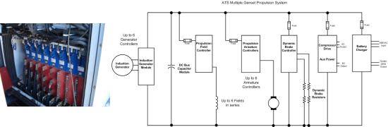
ATS now has 3 induction generator multi-genset systems in operation.

Featuring our bi-directional induction generator controller which provides constant DC bus voltage with variable speed engine control and Smokeless Starting.

Highlights

  • Power is supplied to the DC bus from diesel-driven induction generators. Induction Generator Converters provide excitation for the generators, convert and regulate the output to 750V. The Induction Generator Converters are inherently capable of bi-direction power flow and can be used to start the engines. Additionally, they can also overdrive the engines in order to utilize the engine losses to absorb power from the traction circuits.
  • A pair of interlocked contactors allows the locomotive battery to be connected to the DC bus for the purpose of starting the first engine.
  • The traction armature circuits are controlled by individual chopper modules. The traction field circuit, consisting of all motor fields connected in series, is controlled by a chopper module and a field reversing switch. The reversing switch is operated only while the locomotive is at a standstill and the traction demand is zero.
  • The dynamic braking is controlled by using a chopper module. The armature controllers are permanently connected to the DC bus. During braking, all of the recovered energy is delivered to the DC bus at its normal working voltage. The power recovered is used to supply the auxiliary loads. Also, the generator converters are used to overdrive the diesel engines to a speed slightly in excess of their governor settings. This causes the injector pump to shut off completely, thus allowing the engine cranking losses to be supplied by the recovered braking power. When the bus voltage and the engine speed have reached their upper operating limits, the dynamic brake controller begins to operate and controls the dissipation of the remaining power in the resistor grids.
  • A Fan and Compressor Inverter provides up to 100kW for driving engine cooling fans, traction motor ventilation fans and the air compressor. The frequency is reduced or motors are switched by contactors in order to reduce air delivery as appropriate.
  • A DC-DC Converter and Auxiliary Power Converter delivers isolated power to the 74V control circuits and provides a sinewave, 120V, 60Hz output for air conditioning or other appliances.